Analysis of circuits of DC
The loads in the conductors can move with certain freedom. The electrical current constitutes a continued movement of the free loads. The amount of load that circulates around a conductor in the time unit is the intensity of current. The people in charge to maintain the current in an electrical circuit are the generator ELTS, which provide to the circuit the precise energy for it. Two laws of experimental nature discovered by Ohm and Joule respectively contribute some relations that facilitate the scientific study of the electrical current.
The essential characteristic of the conductors, is these solids, liquids or gaseous, it consists of which they have loaded particles that they can move with enough freedom under the action of electric fields. When an unloaded conductor puts itself in contact with a loaded body takes place a displacement of the load from the one to another one by effect of the electrical forces. If both are isolated, the movement of the free loads will in the meantime last moments the system of loads finds a balance configuration in which the electrical forces that are exerted on each one of the loads compensate mutually. This is what happens when a metallic thread is connected by one of its ends to one single one of the tips of a battery. Nevertheless, when the other end of the conductor to the second tip is connected, a continued movement of loads in the conductor takes place. An electrical current is had in such case. The part of the physics that takes care of the study of this type of movement of the electrical charges through a conductor receives the electrocinética name.
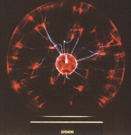
Modeliza plasma globe that the eye of the storm. In plasma globes kV and 50 20 are applied 8 to 3 voltages of kV to frequencies of kHz to kHz between the center of the globe and the outer layer in contact with the Earth.
The presence of a permanent electric field in a conductor is the cause of the continued movement of the free loads. In potential terms it can say that so that an electrical current stays it is necessary that a difference of constant potential between the ends of the conductor exists. If this one diminishes by effect of the circulation of the loads, the electric field gets to become null and stops the movement. This is the situation that corresponds to those displacements of load which they take place when an isolated conductor load or unloading electrically.
Due to his facility of handling, in electrocinética to describe the properties of the field inside a conductor one resorts to the notion of potential difference, also denominated electrical tension because on her the movement of the free loads from a point to another one depends. The sense of the electrical current depends not only on the sign of the difference of potential, but also of the sign of the carrying elements of load or present live loads in the conductor.
In a metallic conductor the load carriers are the electrons (-), reason why their displacement will take place of the end of the conductor to potential minor towards the end to greater potential, or in terms of signs from the negative pole towards the positive. In a saline dissolution the load carriers are positive ions as as much negative; when this dissolution is put under a difference of constant potential, as the produced one between the tips of a battery, movements of load of opposite senses are generated; the positive charges will move by the dissolution of the end of greater potential to the one of potential minor, or what is the same, of the positive pole of the battery to the negative pole, and the refusals in opposite sense. Something similar happens in ionized gaseous means like which it takes place inside a fluorescent tube or of neon submissive an intense difference of potential.
Franklin youngest child was first in assigning a sense of circulation to the electrical current in the metallic conductors. It supposed that it was the positive electricity the one that, like a subtle fluid, moved by the interior of the conductor. According to this supposition, the electrical current would circulate of the positive pole to the negative. More of a century later the modern atomic theory revealed that the electrons are the carriers of load in metals, so that the real sense of the current exactly turns out to be the opposed one to the advanced one by Franklin. By historical reasons and since in the electrocinética the sense of circulation of the current does not have greater importance, it is continued accepting like conventional sense the postulate by Franklin. Nevertheless, in other parts of the physics, like the electronics, the distinction between both is important.
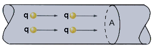
Next to the idea of particle movement, the notion of electrical current takes associate the one of transport of electrical charge from a point to another one. The importance of this transport in amount terms expresses by means of the magnitude intensity of electrical current that is defined as the total load that circulates around the conductor in the time unit. In equation form it is possible to be written like:
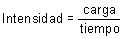
The unit of intensity of current in IF it receives the name of ampere (a) and is equivalent to a transport of load that takes place at the rate of 1 coulomb (c) in every second (s), 1 To = 1 C/s.
In a metal, in where the electrical current must solely to the electron movement, only the transport of negative load contributes to the value of the intensity. In the ionic dissolutions, to the lead being the current as much by positive ions as negative, takes place one double contribution of both types of load to the intensity of electrical current.
In a conductor the movement of electrical charges is consequence of the existence of an electrical tension between its ends. For that reason the intensity of current that circulates around the conductor and the tension or difference of potential must be related. Other phenomena of the physics present/display a certain similarity with the electrical conduction; thus the heat flow between two points depends on the temperature difference among them and the speed of fall of a body by an inclined plane is function of the altitude difference.
That type of analogies, and in individual the relative one to the conduction of the heat, served as departure point the German physicist Georg Simon Ohm (1787-1854) to investigate the electrical conduction in metals. In 1826 it got to establish that in the metallic conductors the quotient between the difference of potential between its ends and the intensity of current that crosses it is a constant amount, or in other terms, that both magnitudes are directly proportional. This relation of direct proportionality between tension and intensity receives the name of law of Ohm.
Representing, as he is habitual in electrocinética, the electrical tension by V and not by  V, the law of Ohm can be written in the form:
I = G · V (10.2)
where G is a constant characteristic of each conductor who receives the conductance name.
Curve characteristic IV is denominated of a conductor to the line that is obtained when the variation of the intensity of current I imagines graphically that crosses a conductor with the potential difference or applied tension V between its ends. Its form is characteristic of each conductor, of there its name.
The experimental determination of a characteristic curve takes place by means of a assembly that allows to apply to the ends of a conductor a any variable tension and that simultaneously makes the measurement possible as much of the tension applied as of the intensity of current that constitutes the answer of the conductor. Some characteristic curves IV are linear, which is equivalent to say that in their corresponding conductors both electrical magnitudes are directly proportional. This is what comes to establish the law of Ohm for the metallic conductors.
In curve characteristic IV of a metallic conductor the slope of the graph agrees with the constant of proportionality G that, in agreement with its definition, constitutes a measurement of the aptitude for the electrical conduction of the considered body. Whichever greater it is G, greater will be the inclination of characteristic IV and, therefore, greater the intensity than will circulate around the conductor for a same difference of potential.
The inverse one of conductance G denominates electrical resistance and it imagines by letter R:

From a physical point of view, resistance R of a conductor constitutes a measurement of the opposition that presents/displays this one to the passage of the electrical current. In metals the electrons have to move through atoms of the crystalline structure of the own metal. Such obstacles to the free movement of the loads contribute, as a whole, to the value of resistance R.
The expression (10.2) can be written, making take part to the resistance, in the form:
V = I · R (10.3)
that it constitutes the most well-known expression of the law of Ohm.
From the previous equation ohm is defined (  ) as unit of electrical resistance in the form:

The fact experimentally observed that all the conductors do not have rectilinear characteristics IV indicates that all do not obey the law of Ohm. Is this one, therefore, a law of restricted character that only can be applied to certain type of called conductors ohmic. In the nonohmic resistance it does not have a constant value, but that this one depends on the tension that is applied between the ends of the conductor.
Experiments with metallic threads of different lengths and thicknesses took to Ohm to establish the concept of resistance when observing that intensity I of current the inversely proportional length l of conductor and directly proportional era to their section S or thickness. When this discovery is combined with the relation of inverse proportionality between R and I that its famous law establishes, is the relation:

where  it is a constant characteristic of the type of metal that constitutes the considered wire. This constant denominates resistivity and is equivalent to a specific strength referred to a length and section unit. Xs are expressed in ohms meter ( · m). The inverse one of resistivity receives the conductivity name and it imagines by the letter
  ( = 1/r). It are expressed in -1 · M-1 and characterizes the behavior of a material like electrical conductor. In metals, it takes values of the order of 107 -1 · M-1 and in typical insulators as the glass or the paraffin reaches 10-14 in the first material and 10-17 -1 · M-1 in the second. The semiconducting materials present/display values of sintermedios.
Since the difference of potential V constitutes an energy by load unit, the law of Ohm can be interpreted in energy terms. The collisions of electrons in metals with the knots of the crystalline network take with himself a dissipation of electrical energy. This phenomenon is the person in charge of the loss or fall of potential V that detects, in greater or smaller measurement, between the ends of a conductor, and indicates that each unit of load loses energy when happening of one to another point to razõacute;n of V Julies through each coulomb of load that crosses it.
If the general principle of conservation of the energy is applied to the electrical phenomena, the law of Ohm, defined by the expression (10.3), can be considered like a conservation equation in where the first member represents the lost energy in the circuit by each unit of load in movement and the second the yielded energy the outside by each coulomb who circulates between the considered points.
The movement of electrons by a metallic conductor as a result of a difference of potential between its ends can be compared with the water flow between deposits located to different height and connected by means of a pipe. When the water fills to the superior deposit descends, but this movement lasts only in as much stays a difference between the water levels in both deposits. In order to maintain the water in continuous circulation a pump is necessary intercalary that again elevates the water from the inferior deposit to the superior one. The paper of the pump in this hydraulic circuit is the one to communicate to the mass of water that crosses the sufficient energy like both saving the altitude difference between deposits, which is equivalent in fact to even maintain constant the difference of levels of the water between both deposits in spite of the continuous flow that crosses them.
In order to maintain an electrical current inside a conductor it is precise that a difference of constant potential between its ends exists; it is necessary, then, a device that plays an analogous role the one of the pump in the hydraulic circuit. This device receives the generator name. An association of conductors with a generator constitutes an electrical circuit in where a continued movement of loads can take place. The generator maintains constant the difference of potential between two points of the circuit, or said in other terms, it generates an electric field in the conductor who is the person in charge of the current.
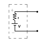
The electromotive force is the magnitude that characterizes the behavior of the generator in an electrical circuit. In the case of a hydraulic pump the mechanical power represents the energy that it provides to the circuit by time unit. In the electrical circuits the electromotive force of a generator is defined and it imagines by means of the letter and, like the energy that yields the generator to the circuit by each unit of load that crosses it and that is reversed in increasing its electrical potential energy. Each load when happening through the generator receives a dose of energy that will be able to spend later in its route throughout the circuit.
Frequently, the initials are used f.e.m. to designate this magnitude, that being an energy denominates force impropiamente. According to its definition f.e.m. it will be expressed in power units divided by load units. This it is also the case of the magnitudes potential and difference of potential. By such reason its unit in IF it is the volt.
The type of generators more known is the chemical generator, to which it belongs the electrical battery or it pounds dry. It transforms produced energy into certain chemical reactions in electrical energy able to maintain a difference of constant potential between his poles or tips. A battery zinc-coal, like that they are used to feed a portable radio, is formed by two elements or electrodes of different substances. One is of zinc and has form of cylindrical envelope, the other is a barrita of coal. Between both an intermediate paste or electrolyte exists that contributes to the process of tension generation. The chemical reaction that takes place in the zinc electrode releases electrons, with which this one becomes a negative pole (cathode); the one that one takes place in the coal electrode it gives rise to an electron diminution, being from positive sign (anode). The tension produced by a battery is constant and when applying it on an electrical circuit it produces a DC. This type of current is characterized because the sense of the movement of the load carriers stays constant.
The fuel battery is another type of chemical generator of frequent use in the provision of electrical energy to spaceships. It receives east name because the substances that participate in the corresponding chemical reactions are, partly, introduced from the outside as if a fuel one was. A typical fuel battery is the one that is based on the reactions hydrogen oxygen that take place with loss of electrons in an electrode and gain in the other, giving rise to a difference of potential able to produce an outer electrical current.
A thermocouple is a thermoelectrial generator that transforms heat into electricity. One of the flux ice welds takes place when two united wires to each other by their respective ends are put under a temperature difference, submerging and applying to the other the flame of a burner. Between both points a potential difference is generated that increases with the temperature and can be detected with an electrical measuring instrument. This generating effect of known electricity as Seebeck effect is used mainly in the measurement of temperatures.
The photovoltaic cell is a generator of photoelectric type that transforms the lúminosa energy into electrical energy. One is based on, capacity of the semiconductors to lead the electricity in a given sense, but not in the opposite one. When affecting the light the cell, takes some electrons of its atoms, electrons that are accumulated in a region determined to expenses of the loss of electrons in the opposite region.
Like in a dry battery, these two regions constitute the poles negative and positive, respectively, of the cell whose difference of potential will stay constant in as much does not vary the light intensity that reaches its surface.
The electromagnetic generator is based on the phenomenon of the electromagnetic induction. When a closed conductor rotates itself in the magnetic field produced by a magnet is generated in his interior a difference of potential able to produce an electrical current. It is the type of denominated generator alternator that is used in the great plants of production of electrical energy.
In them, different forms from energy, whose nature depends on the type of power station, are reversed in moving great coils of conductors, doing to turn them in magnetic fields. This way electrical tensions between their tips take place whose positiva/negativa polarity, is reversed alternatively with time at the rate of fifty times in every second. When this tension is applied to an electrical circuit, it produces in him an alternating current that is characterized by an alternative investment, with identical frequency, of the sense of the movement of the load carriers.
They are two electrical measuring instruments that can be considered like modified galvanometers. First it is used to measure differences of potential between two points nobodies and the second to measure intensities. Its presence in the scheme corresponding to an electrical circuit imagines in the form - v and - To respectively.
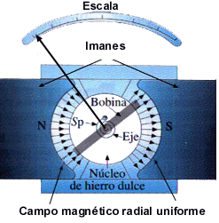
The galvanometer, whose name honors to Galvani, takes advantage of the magnetic effect the electrical current. It consists, in essence, of a magnet between whose poles a coil is arranged that can turn perpendicularly on an axis ready to the plane of the magnet.
A shared in common needle with the frame of the coil makes visible, on a graduated scale, the possible movement of that one. This movement is crippled in absence of current by two return springs or means in spiral. When it is made pass a current through the coil, it appears a magnetic force between the coil and the magnet that as much turns aside the needle of its starting point plus whichever greater is the intensity of current.
An ammeter consists, basically, in a galvanometer with a shunt or resistance in parallel with the coil, of magnitude the sufficiently small thing like obtaining that practically everything, the current is turned aside by her and who the measuring instrument disturbs the less possible conditions of the circuit. The amperímetros are connected in series with the circuit, that is to say, they are put in between the points in where it is desired to measure the intensity.
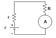
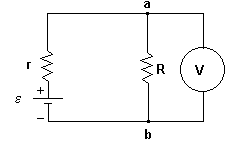
A voltmeter comes to be a galvanometer with an important resistance associated in series with him. The set connects in parallel or derivation between the points whose difference of potential is desired to measure. If the total resistance of the voltmeter is much greater than the one of the circuit, between such points the current will be derived to a large extent by the section that offers minor resistance to its step and only one fraction from her will cross the voltmeter. With it it is obtained that the disturbance that introduces in the circuit the measuring instrument is despicable.
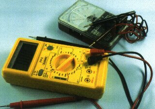
Often, these two devices and ohmímetro are including in a called device Multímetro, that is connected according to the use of each one of them. At the moment they are possible to be encontar Multímetros digital as as much analogical. The digitalises are generally exáctos (and more expensive) than the analogical ones.
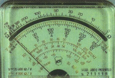
Analogical Polímetro
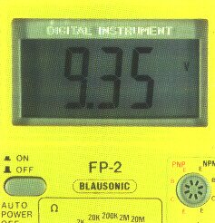
Digital Polímetro
Two rules exist, calls Laws of Kirchhoff, that are applied to any circuit in stationary state:
1. The algebraic sum of the variations of potential throughout any curl or mesh of the circuit must be equal to 0.

2. In a point or knot of ramification of a circuit in where the current can be divided, the sum of the current months which they enter the knot must be equal to the sum of the current months that leave the same one.

Rule 1, called Rule of the meshes, is deduced from the simple fact that in the stationary state the difference of potential between two points nobodies is constant. In stationary state, the electric field in any point (outside a source of fem) is due to the accumulated load on the surfaces of the tips of the battery, resistance, cables, or other elements of the circuit. As the electric field is conservativo, a potential function in any point of the space exists (except inside a source of fem). According to we moved throughout the mesh and it has been arrived at the point from which it was begun, the net variation of the potential must be equal to zero. This rule is a direct consequence of the conservation principle of the energy.
The second rule of Kirchhoff, Rule of the knots, is deduced of the conservation of the load. This rule is necessary for circuits of multiple meshes that contain points in which the current can be divided. As in stationary state there is no later accumulation of electrical charge in no point of the circuit, the amount of load that enters a point, it must be equal to that leaves this point.
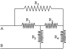
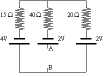
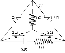
Ej: Given the following circuit.
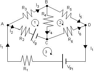
When writing the first law, we must consider those currents that leave a knot like positive and those that arrive like refusals. The first law expresses the conservation of the load because, as the loads are not accumulated in a knot, the number of loads that arrive at a knot in a certain time must be equal to the number of loads that leave in the same time.
When applying the second law we must take into account the following rules. A fall of potential through a resistance is positive or negative according to which we cross the circuit in the sense of the current or opposite sense. When we happened through one fem, we took the difference from potential like positive refusal or depending on which we cross it in the sense in that fem acts. The second law expresses the conservation of energy, since the net variation of energy of one loads after to have crossed a closed way must be 0.
We applied these laws for this circuit.
The first law applied to the knots To, B and C gives:
Knot A: - 32Is1+I+I= 0
Naked B: - 543Is+I+I= 0
Knot C: - I2 - 64Is+I= 0
The second law applied to routes 1.2 and 3 gives:
Route 1: - R22Is+R33Is+R4Is4- =0Sees 2
Route 2: R5Is-R 65Is6- R44Is= 0
Route 3: R1I1+R22Is+R6Is6- +Ve2Sees1= 0
These 6 equations are sufficient to determine the six currents in the network.
An electrical circuit is formed by the association of a series of conductive elements that make the maintenance by their interior of an electrical current possible. If the generators produce a difference of constant potential between their tips or poles, the produced current will be continuous. So it is the case of the batteries and the batteries.
In the circuits of DC two types of elements can be distinguished basically, the generators and the receivers. First they contribute to the circuit the energy necessary to maintain the current electrical, the seconds they consume electrical energy and, or dissipate it in heat form, as is the case of the resistance, or they turn it another form of energy, as it happens in the motors. A battery in an electrical circuit imagines by means of the symbol  that reflects the polarity of the generator. A resistance imagines by the symbol
  .
.
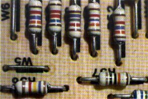
In order to simplify the study, one assumes that the magnitudes or parameters characteristic of these elements are concentrated in the points of the circuit where they imagine. Thus, the resistance of connection cables or not deigns or it assumes concentrated in a point as if it was a circuit element more.
The quantitative study of the electrical circuits of DC takes place like an application of two basic principles:
The principle of conservation of the energy referred to the unit of electrical charge, according to which in all the circuit, or any section of him, the energy that loses the electrical current is equal to the energy yielded by the circuit to the outside. It is, in essence, the law of Ohm generalized and interpreted like balance of energies.
The principle of nonaccumulation of loads, that it indicates that the loads cannot be accumulated. That means that if there are no bifurcations, the intensity of current is the same one in all the circuit, and if there are them, the intensity of current that a knot or junction enters has to be equal to the sum which they leave him.
Such principles are also known like laws of Kirchoff.
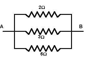
Two ways fundamental exist to connect or to associate the resistance to each other, in series and parallel or derivation. In the association in series the resistance connect one after another one so that through all of them passes the same intensity of current. In the association in parallel the connection takes place uniting both extreme of each one of them to a same pair of points. In this case the difference of potential between the ends of anyone of the associate resistance is the same one, but, in agreement with the principle of nonaccumulation of loads, the total intensity that arrives at the knot or junction distributes among them.
Resistance equivalent of an association of resistance is denominated to that unique resistance by which the association without altering the intensity could be replaced that circulates around the circuit. In the case of an association in series of three resistance, the formula of the equivalent resistance Re is obtained as it follows. In agreement with the law of Ohm applied to each one of them, it is had:
V1 = I · R1; V2 = I · R2; V3 = I · R3
where V1, V2 and V3 are the tensions between their respective ends and I the intensity of current that crosses them, equal for all of them.
In agreement with the principle of conservation of energy referred to the load unit, the total amount of energy that loses the unit of load when crossing the three resistance will be equal to the sum of the amounts that loses in each resistance, is to say:
V = V1 + V2 + V3 = IR1 + IR2 + IR3 =
= I · (R1 + R2 + R3)
If the law of Ohm is applied to the association as a whole, it is had
V = I · Re
Comparing both equations it is:

Equation that can become general to any number of resistance.
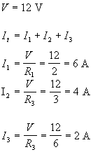
If the association went in parallel, when arriving at the knot the current is distributed between the different resistance and, in agreement with the principle of nonaccumulation of loads, it will be fulfilled, in this case, the relation
I = I1 + I2 + I3
with
V1 = V2 = V3 = V
Applying the law of Ohm to each resistance, it is now:
V = I1 · R1; V = I2 · R2; V = I3 · R3
For the association as a whole it will be had:
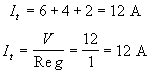
V = I · Re
If the values of I are replaced, I1, I2 and I3 in the equation of the intensities are obtained:
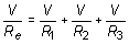
it is to say:
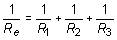
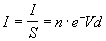
In this case it is the inverse sum of the the one that gives rise, not to the equivalent resistance, but to its inverse one. By such reason in this type of association the value of the Re, turns out to be inferior to the one of smallest of the associate resistance.
In the study of the behavior of anyone of the parts or the elements of a circuit, one needs to know which is the intensity of current that circulates around him. The determination of the intensity or intensities of current that circulates around all and each one of the elements of a given circuit receives the name of circuit analyses.
In the case of simple circuits with a single generator, or several associate in series, it is possible upon maturity to take to the analysis of circuits applying of general form the principles previously considered, as well as the formulas of association of resistance. Nevertheless, when several generators distributed by different bifurcations or branches exist the problem from the complica analysis and is precise to resort to more powerful and also more laborious procedures.
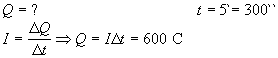
The law of Joule allows to calculate the energy dissipated in heat form in a conductor. Its mathematical expression is Q = I2 · R · t, being R the resistance in ohms, I the intensity of current in amperes and t the time in seconds.
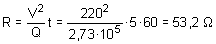
In order to elevate the temperature of the water in 1 ºC 4.2 are needed J by each gram. One is to determine, applying the law of Joule, the value of the electrical resistance that must have an electrical heater so that, connected to a plug of 220 V, is able to elevate the temperature of a liter of water of 15 ºC to 80 ºC in five minutes.
The calorific energy necessary to elevate the temperature of the water of 15 ºC to 80 ºC will be:
Q = 1000 · (80 - 15) · 4,2 = 2,73 · 105 J
then a liter of water corresponds to a kilogram of mass and 4.2 represent the heat in joules by gram and degree Celsius (heat capacity).
Since it is had the value of the tension, but not of the Intensity, it will be necessary to transform the law of Joule so that in the corresponding formula she appears that one and not this one. Resorting to the law of Ohm V = I · R is had:
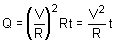
Clearing R and replacing the well-known values it is:
The electrical energy Wand that provides a generator to the electrical circuit depends on the amount of load that crosses it. Since the electromotive force of a generator represents the energy that it provides to the circuit by each unit of load that crosses it, it will be possible to be written:

it is to say:
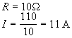
But in agreement with the definition of electrical intensity, electrical charge q can be written like the product of the intensity by time (10 · 1); soon the electrical energy provided by the generator to the circuit in a time t will come given by the expression:

The P power of a generator represents the electrical energy that yields to the circuit by time unit, is to say:


Combining the previous equations the expression is for P:
|
|
|
Like the mechanical power, the electrical power is expressed in watts (W).
Thermal effects of the electrical current. Law of Joule
The heating of the conductors by the passage of the electrical current was one of the first effects observed by the studious scientists of the electrical phenomena, nevertheless, would have to spend some time before it knew the magnitude such thermal effect and the factors on which it depends. J. P. Joule (1818-1889) one was interested from young person in the measurement of temperatures of electrical motors, which allowed towards 1840 to find the law him that governs the heat production by the passage of an electrical current through a conductor.
The law of Joule establishes that the produced amount of heat is directly proportional to resistance R of the conductor, to the square of the intensity of current I that crosses it and to time t. It is to say:
Q = I2 · R · t (10.8)
The thermal effect, also call Joule effect, can be explained from the mechanism of conduction of electrons in a metal. The energy dissipated in the internal shocks increases the agitation thermal of the material, which gives rise to an increase of the temperature and to the consequent production of the heat. The law of Joule, on the other hand, can be focused like a consequence of the power interpretation of the law of Ohm. If I · R represents the energy dissipated by each unit of load, the total energy that dissipates in the conductor in heat form, when it has been crossed by a load q, will be:
Q = q · I · R
But since q = I · t, is had finally:
Q = I2 · R · t
that it is indeed the law of Joule.
The calorific power represents the heat produced in a conductor in the time unit. Its expression is deduced from the law of Joule in the form:
 |
 |
Since the heat is an energy form, it express in joules (j) and the calorific power in watts (W).
When equations (10.9) are combined and (10.3) is another expression for the consumed electrical power in a conductor:
P = TO GO · I = I · V (10.10)
Electromotive force and difference of potential
The notion of electromotive force of a generator like energy that communicates the circuit by each unit of load that crosses it, is referred an ideal or pure generator. In such case all the energy that produces the generator yields al completely circuit, by as the electromotive force and exactly agrees with the difference of potential V constant that maintains between its tips:
 |
 |
In fact, a battery, a battery or an alternator are in themselves conductive elements that comprise of the circuit through where it passes the current and in greater or smaller measurement they oppose, like such, a certain resistance to the movement of the loads.
It means that the generator, when forming part of the circuit, is warmed up and dissipated, therefore, a certain amount of heat. The idea of energy balance to which it is equivalent the interpretation of the law of Ohm in power terms can then extend to the case of a generator in order of finding the relation between and and V in this new situation. Applying the conservation of the energy by load unit to the ends of the generator, it is had:

that in form of symbols it turns out to be:


This equation knows as law generalized Ohm a generator and allows to determine the potential difference that is able to maintain between its tips a real generator, that is to say, with nondespicable internal resistance r.

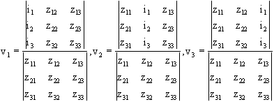
Where à ZII : Sum of all the resistance of a mesh.
Zij : Sum of the resistance that shared by mesh i and
mesh j
z > 0 if Isi and Ij have the same sense.
z < 0 if Isi and Ij have different sense.

Where à Vi : Sum of voltages V in mesh i.
V > 0 if Ii leaves the power supply by tip +.
V < 0 if Ii enters the power supply by the tip -.
(the sign of exit of the power supply is watched.)

In our case:

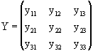
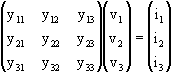
andiiº sum of all the admittances of knot i
andijº sum of the admittances shared between knots i and j
andij < 0 always
Example:
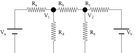
and11= 1/Rto+1/Rd+1/Rb, and12= - 1/Rb, and21= - 1/Rb, and22= 1/Rd+1/Rc+1/Re
and13= and31= and23= and32= and33= 0

ii= sum of the intensities applied to knot i
I>0 if the currents enter the knot
I<0 if the currents leave the knot
Example:
i1= 2Vto/Rto,is= Vb/Rc, 3is= 0
The superconductivity is a property which they present/display some materials submissive certain special conditions, to lead the electricity without offering no resistance and, therefore, without dissipating energy by Joule effect. Even though the phenomenon of the superconductivity was discovered by Kamerlingh Onnes in 1911, until only years ago was necessary, to obtain such property, to put under certain metals to temperatures next to the zero absolute one (- 273 ºC).
Recent investigations have been able to synthesize materials of ceramic type able to become superconducting to much more high temperatures. The wild scientific race that has untied in this field allows to lodge the hope to obtain, in the short term, superconducting materials to temperatures very next to the atmosphere.
The importance of this scientific profit can be decisive in a good number of technical applications. It is possible to emphasize the possibility of making electromagnets with superconducting with a reduced cost, which would lower the price of the construction of some sophisticated apparatuses of medical diagnosis which they use powerful magnets, would facilitate the production of the energy of the future and would allow to construct high speed and economic means of terrestrial transport based on the sustenation or magnetic levitation. A German experimental train of these characteristics has obtained to a speed of 406 km/h. This type of trains, when moving without making contact with enemy with the ground, avoids the undesirable effects of the friction and is equivalent to airplanes that move in grazing flight.
 |
 |
 |
 |
||
| PRINCIPAL | ELECTRÓNICA | INFORMÁTICA | TECNOLOGÍA | ||
| Ciencias Místicas - www.cienciasmisticas.com.ar - El sitio de electrónica, informática y tecnología. | |||||