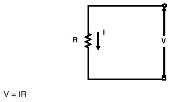
FIGURE 1. OHM LAW
Equivalent circuits
Laws of Ohm, Kirchoff, Thevenin and Norton
Equivalent circuit of one dice is another fictitious one that, seen from its terminals, BUCKET just as the dice.
Said of another way, it is a mathematical artifice by means of as one is able to study the behavior of a circuit by means of simpler other.
The equivalent circuit is not just as the original one: only its behavior towards the outside is just as the one of the original one.
LET US REVIEW: The Laws of Ohm and Kirchoff
The Law of Ohm establishes the relation that exists between the current in a circuit and the difference of potential (voltage) applied to this circuit.
This relation is a function of a constant to which resistance was called to him.
FIGURE 1. OHM LAW
1ª Law of Kirchoff establishes that the algebraic sum of the voltages around any closed curl is equal to zero.
The sum includes independent sources of tension, dependent sources of tension and falls of tension through resistores.
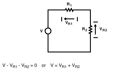
Sumatoria de Fuentes de Tensio'n = Sumatorio of tension falls
FIGURE 2. 1ª KIRCHOFF LAW
2ª Law deKirchoff establishes that the algebraic sum of all the current months that enter a node is equal to zero.
This sum includes the sources of independent currents, the dependent sources of current and the currents through the components.
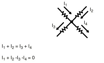
The sum of current months that enter a node is equal to zero FIGURE 3. 2º KIRCHOFF LAW
Splitters of Tension and Current
The splitters of Tension are used frequently in the design of circuits because they are useful to generate a reference voltage, for the polarization of the active circuits, and acting like refeeding elements.
The current splitters see with less frequency, but they are the sufficiently important thing like so that we study them.
The equations for the tension splitter, in where we suppose that there is no load connected to our circuit are seen in Figure 4.
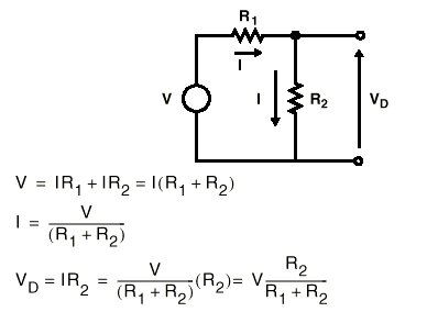
FIGURE 4. TENSION SPLITTER
The equations of the current splitter, supposing that the load is only R2, come given in Figure 5.
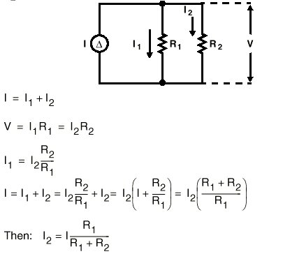
FIGURE 5. CURRENT SPLITTER
Theorems of Thévenin and Norton
There are situations where he is simpler to concentrate part of the circuit in an only component one before to write the equations for the complete circuit.
When the entrance source is a tension generator, the theorem of Thévenin is used to isolate the interest components, but if the entrance is a generator is used the theorem of Norton.
THEVENIN THEOREM
Any circuit, by complex that is, seen from two concrete terminals, is equivalent to an ideal generator of tension in series with a resistance, such that:
- The electromotive force of the generator is equal to the potential difference that is moderate in circuit opened in these terminals
- The resistance is the one that "is seen" TOWARDS the circuit from the terminals at issue, cortocircuitando the tension generators and leaving in open circuit those of current
In order to apply the theorem of Thévenin, for example, in the case of Figure 6, we chose points X and and and, we suppose that we disconnected everything what we have to the right of these points, (that is to say, we are supposing that the resistance R3 and R4, we have disconnected them physically of the original circuit) and we watched back, towards the left.
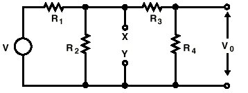
FIGURE 6. ORIGINAL CIRCUIT
In this new situation we calculated the tension between these two points (X,Y) that we will call the equivalent tension Thévenin Vth that agrees with the tension in tips of the R2 resistance and whose value is:
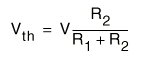
The following step is, being we located in the indicated points (X and) to watch towards the left and to calculate the resistance again that we see, but considering that we must suppose that the tension generators are short circuits and the generated ones of current are opened circuits, in the case of our original circuit, only there is a tension generator that, for the calculation which we must do we will suppose in short circuit and that it is what we see?
Then if you watch figure 6, which we see is that, the resistance R1 and R2 are in parallel.
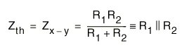
Reason why the equivalent resistance Thévenin, also call equivalent impedance, Z th. it is worth:
The circuit studied to the left of the points X, and is replaced now by the equivalent circuit that we have calculated and we have left the circuit of figure 7, where now is much more easy to make the calculations to obtain the Vo value
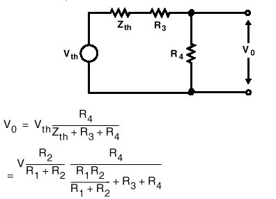
FIGURE 7. EQUIVALENT CIRCUIT THEVENIN
The other form to calculate Vo is, the one of the theory of meshes, that we calculated in figure 8 and where we observed that the results are such. But the resulting equations are enough more laborious.
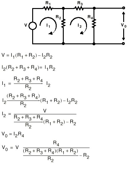
FIGURE 8. ANALISIS Of the SAME CIRCUIT of
FIGURE 6 BUT APPLYING THE EQUATIONS BY MESHES
Therefore, we have observed which, applying the Theorem of Thévenin for the analysis of circuits, we will be able to simplify our calculations, which will be to us always very useful, mainly, in other more complex circuits.
Superposition
The superposition principle establishes that the equation for each independent generator can calculate separately, and then the equations (or the results) can be accumulated to give the total result. When we use this principle of superposition the equation for each generator calculates with the other generators (if they are of tension: they are cortocircuitan; and if they are of current they leave in open circuit). The equations for all the generators are accumulated to obtain the final answer.
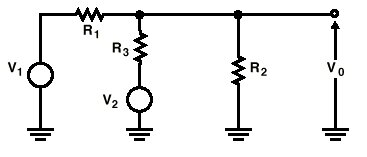
FIGURE 9. SUPERPOSITION EXAMPLE
In the first place the tension of Vo exit calculates, provided by generator V1, supposing that generator V2 is a short circuit. To this tension thus calculated we will call V01 (when V2 = 0)
Next the tension of Vo exit calculates, provided by generator V2, supposing that generator V1 is a short circuit. To this tension thus calculated we will call V02 (when V1 = 0)

The value of Vo will be equal to the sum of obtained valuesV 01 +V 02 previously.

THEOREM DE NORTON
Any circuit, by complex that is, seen from two concrete terminals, is equivalent to an ideal generator of current in parallel with a resistance, such that:
- The current of the generator is the one that is moderate in the short circuit between the terminals at issue.
- The resistance is the one that "sees" TOWARDS the circuit from these terminals, cortocircuitando the tension generators and leaving in open circuit those of current-(It agrees with the equivalent resistance Thévenin)
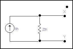
FIGURE 10 EQUIVALENT CIRCUIT NORTON
Applying the Theorem of Norton to the circuit of figure 6, we will have left the following circuit:
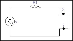
Where we have cortocircuitado points X and of figure 6. The current that circulates among these two points we will call Ith and logically he is equal to tension V of the generator of tension divided by the resistance R1 (Law of OHM) Ith = V/Rthe 1 Thévenin resistance is the same one that the calculated one previously, that was the parallel of R1 and R2
Zth = R1//R2 = R1 x R2 / (R1 + R2)
EQUIVALENCE BETWEEN THEVENIN And NORTON
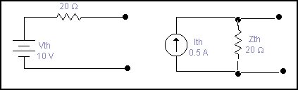
Be as the equivalent one is obtained is very easy to happen to the other equivalent one immediately than to apply the corresponding theorem, thus for example, we suppose that we have calculated the equivalent Thévenin of a circuit and have obtained the circuit of the left of the following figure:
Applying the theorem of Norton to the figure of the left, cortocircuitaremos the exit and we will calculate the current that happens among them who will be the current: 0.520 Is th = 10 / = A. and the resistance 20 Norton is W. reason why we will have left to the equivalent circuit Norton of the right
 |
 |
 |
 |
||
| PRINCIPAL | ELECTRÓNICA | INFORMÁTICA | TECNOLOGÍA | ||
| Ciencias Místicas - www.cienciasmisticas.com.ar - El sitio de electrónica, informática y tecnología. | |||||