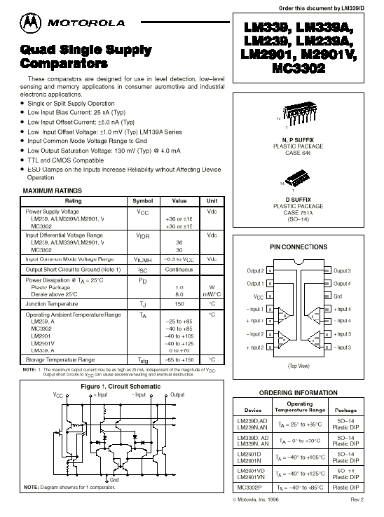
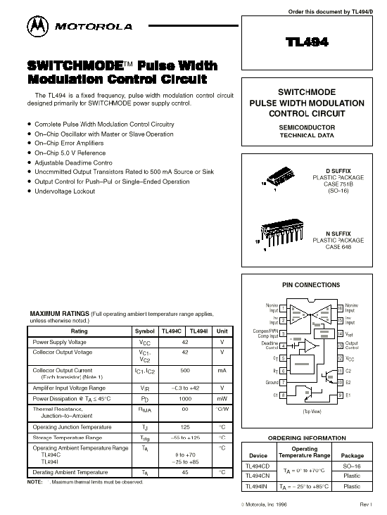
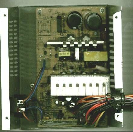
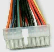
These notes are based on the experience, indicating by area which is due to change to solve the failures, being based on opposite readings to the engineering specifications of each component and according to the symptoms of the source in the area of the primary one like of the secondary one as much.
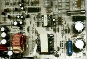
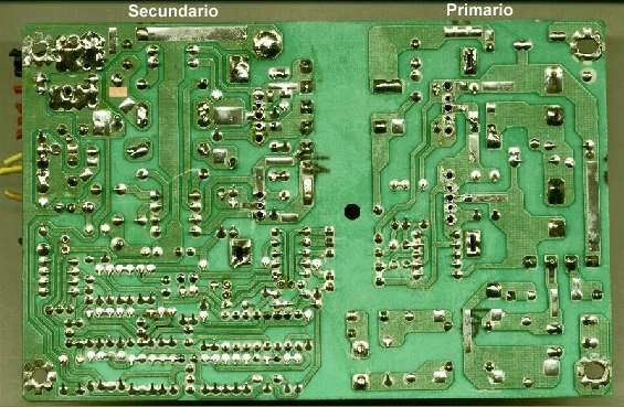
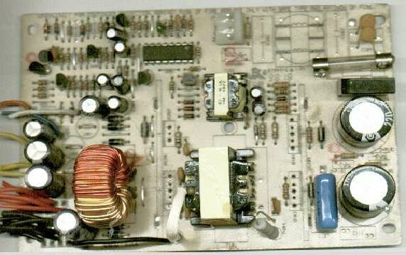
NOTE: In the following images will be a source scanned without the corresponding transistors of the primary area, like the rectifiers of the secondary area of the same one, so that it is appraised better the small components. It has been denominated primary to the entrance of the source (primary of the transforming) and secondary to the corresponding part when coming out of the source.
Primary
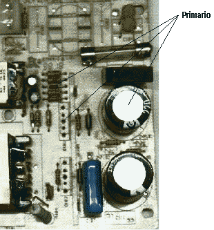
1. Burned fuse
Before changing it is necessary it to review if the rectifying bridge is in short circuit: with multímetro in verification of diodes, and listening to the sound, it is necessary to verify the short circuits (zero reading). It to connect tester both proving in all the senses between pins of the four that the bridge has, or, if it is a bridge of four diodes, each one of them. If this badly or with differences in the measurements it is necessary to change it.
Soon it is necessary to verify the transistors without desoldar them, do not have to never be in short and always with the same measurements among them, that is collector with base, just like the collector with the base of the other. In this case it is necessary to change them if they present/display flights.
There is continuation are an electrolytic set of resistance, condensers and diodes that appear of two in two, that is two of 2 or 1,5 ohm, 2 diodes 1n4140, 2 10 electrolytic condensers of mf, etc. Including the great one of the right, normally of 220 mf x 200 volts or similars.
Each one of them goes in the same way connected, between a transistor and the other. It means that when measuring in the same sense of the exit to measure, with the ends of multímetro in the same direction of connection with respect to the transistors, the measurements must exactly be equal. In opposite case it is necessary to remove the component outside and to measure it, for it can be only desoldar the leg easiest to accede and ready.
This it is all the mystery of the primary area and those measurements are due to do of this form, since any component that this in short in that area would make fly the transistors and serious a cycle never to finish.
2. Healthy fuse
It is exactly just as before, since normally the fuse is not burned but one of the components is opened, like the transistors, and they are not in short.
Some times, if the source works specially intermittent and in cold, it does not start or it makes after several times ignite it and extinguish it. This is motivated by the small diodes 1n4140 or similars that have flight or condensers that are almost dry.
Secondary
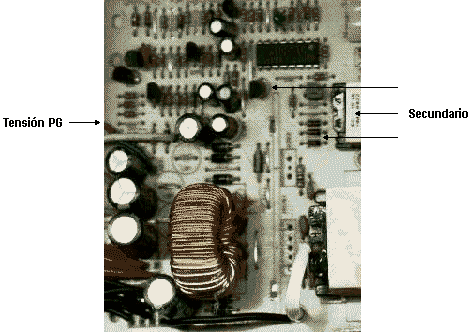
Since we have commented previously, some times if the source works intermittent, specially in cold, it does not start or it does after several attempts. This is because the diodes 1n4140 or similars have a flight, or the small condensers are almost dry. In the secondary one of trafo small, where one is fulfilled just like in the primary area, that is it has two transistors, diodes 1n4140 and small condensers, it is necessary to verify flights raising one of the pins of each component.
The small transistors, following the order of their characteristics with multímetro, seem to have their correct values but it is that in both it must not nevertheless have resistance between collector and emitter and, making pulses with the ends of tester between the mentioned pins, multímetro marks very high flights fleetingly. Replacing the transistors it will be solved to the problem of cold start and other problem.
It is necessary to verify if there is a short circuit in each one of the exits of cables rojo/amarillo/azul and target, that correspond respectively to +5 +12 -5 and -12. Of being thus it is necessary to follow the circuit raising component and verifying them, which only can have is a measurement of R in parallel with the masses (black cable) of between 40/300 ohm, and not a short clear good.
If we verified that everything is or but the plate mother does not work or makes equal, is that something has gone to us.
Tension of PG
It lacks most important. At the end of the repair the most important measurement of the tensions is the denominated tension PG, control tension. All the sources have it and is the cable orange, or of another color, that in the plate of the source can or not be identified but it is the cable that exceeds when coming out of the source and it does not respond previously to any of the mentioned tensions. This tension, being loaded with a lamp of 12 40 volts watts, must give 5 volts positive (red cable) with one of black cables of mass. If tension PG is not equal to 5 volts, or he is not present, it is necessary to follow his connections. Surely we will have some flight or will be responsible some small transistor or false contacts. Some times it is necessary to change the CI of control, a other resistance outside value, and even it can that one of the capacitores small in the primary area causes that single one of the great transistors works one, causing that the tensions of +12 were present but not therefore the rest.